Used Semiconductors: TEA1530AP – STP7NK80ZFP (FET) – OZ9933 – PAM8603MDER
CCFL LCD SAMSUNG 20"W HD+ None Glare LTM200KT03 TBD LF 250nit
5ms 1000:1 2 CCFL(acer B/S) [LK.20006.006]
CONTROL BOARD [55.LBJ0Q.004]
POWER BOARD SEC AUDIO [19.LHC0Q.001]
MAIN BOARD SEC DUAL WITH SPEAKER [55.LHC0Q.001]
POWER CORD US [27.LDW0Q.003]
DVI CABLE [50.LBJ0Q.001]
CABLE BETWEEN CONTROL BOARD AND M/B [50.LHC0Q.001]
CABLE BETWEEN M/B AND POWER BOARD [50.LE10Q.001]
CABLE BETWEEN M/B AND LCD PANEL [50.LGP0Q.001]
SIGNAL CABLE [50.LBJ0Q.002]
STAND BASE DUAL [60.LDX0Q.010]
X203H is defined as new 20’W model in ACER V series which will be
the ACER project in Qisda. X203H is defined as 20’W LCD Monitor supports
1600(H) x 900(V) resolution with DPMS (Display Power Management System) and
ACER eColor function. There are double input types, D-sub, and DVI. X203H
adopts SEC LTM200KT03 and LGD LM200WD1-TLC1. V203H has included 1W+1W
speaker.X203H also support ACM 10000:1
Circuit operations
A basic operation theory for this interface board is to convert analog signals of Red, Green and Blue to digital signals of Red, Green and Blue. The scaling IC has internal A/D converter, internal OSD, built in LVDS transmitter and auto-detect input timing functions. A/D converter is convert analog signal to digital data. OSD is offering adjustable functions to end-user. Detect timing is for detect change mode. LVDS transmitter is used to compress the digital RGB data, the Hsync, Vsync and pixel clock generated by Scaling then output to LCD module. MCU stores source code and offers H/W DDC2Bi function & controls system processing. EEPROM is stored DDC and HDCP data, OSD common data and user mode
data.
DDC (Display Data Channel) function
Use DDC IC to support DDC2Bi function. DDC data is store in 24C02
(EEPROM). Those data related to LCD monitor specification. PC can read them by
“SDA” and “SCL” serial communication for I²C communication for DDC2Bi.
Scalar IC
Scalar IC
There are A/D, TMDS receiver, HDCP, Scaling, OSD and LVDS
transmitter functions built-in the RTD2545LH IC. Scaling IC is revolutionary
scaling and color engine, capable of expanding any source resolution to a
highly uniform and sharp image or down scaling from 1980x1020, combined with
the critically proven integrated 8 bit triple-ADC and patented Rapid-lock
digital clock recovery system. It also support detect mode and DPMS control.
RTD2120L
RTD2120L
Control unit, it controls all the functions of this interface
board, just like the OSD display setting, the adjustable items, adjusted data
storage, the external IIC communication, support DDC2Bi. .
EEPROM
EEPROM
Use 24C016 to store all the adjustable data, user settings and
HDCP Key and use 2 of 24C02 to store DVI and D-SUB EDID data.
Enter factory mode (press “Empowering” & “Power” buttons at
the same time to turn on monitor)
Timing adjustment
1. Enter factory setting area (press “Empowering” and then press “SOFTPOWER”).
2. Check the settings to following values:
Contrast = 50
Brightness = 85
Color = Warm
Language = English
Then, turn off the monitor power.
3. Turn on power enter user area.
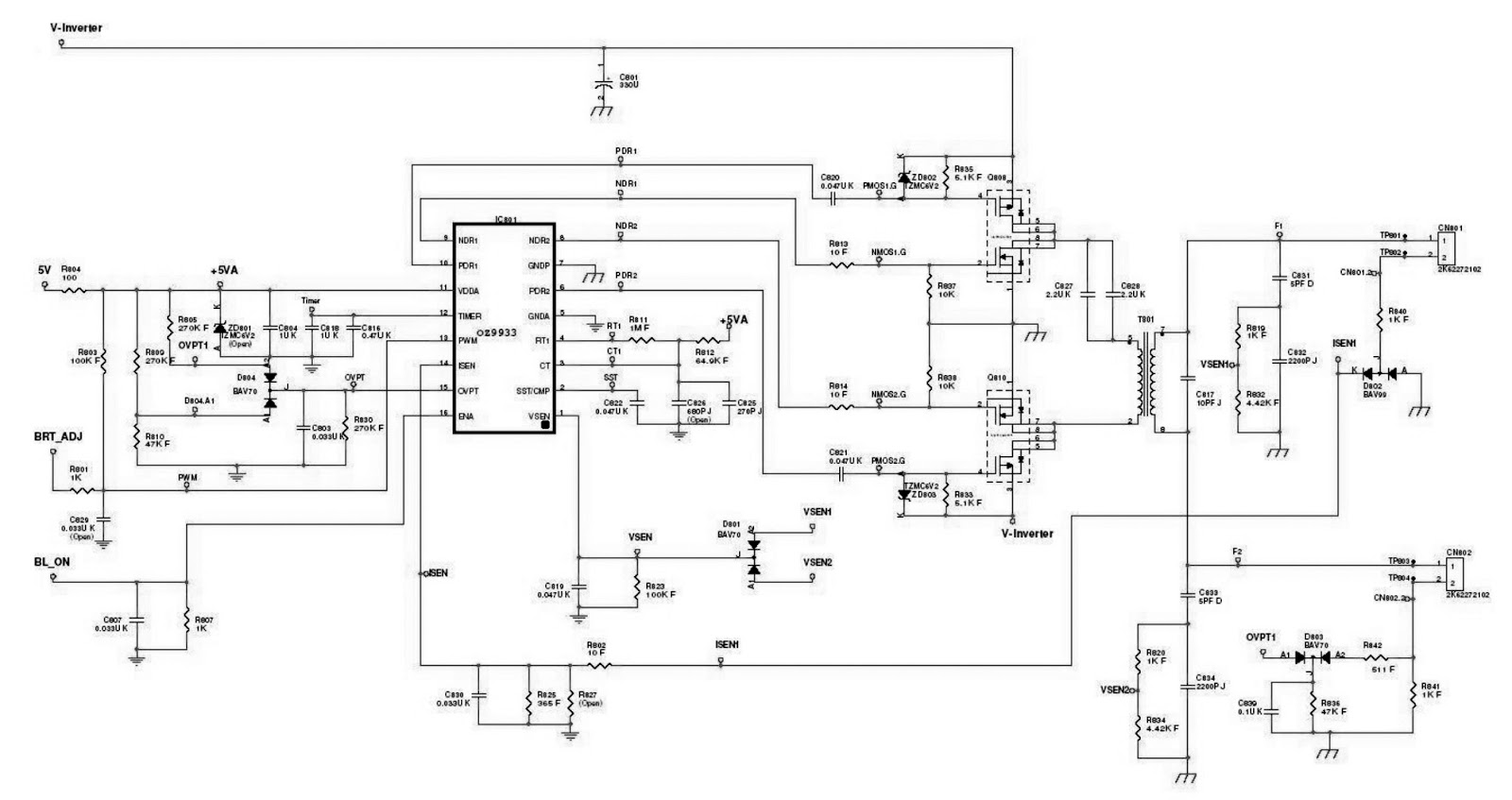
SMPS and back-light inverter circuit diagram


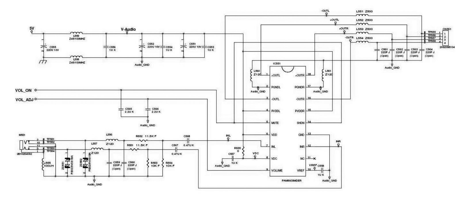
Audio output
Firmware Upgrade Procedure
Step 1: Un-zip Port95nt and install into your computer.
Step 2: Un-zip ISP application tool (RTDTool)
Step 3: Press “RTD 2120 ISP” button to execute firmware program application.
Step 1: Un-zip Port95nt and install into your computer.
Step 2: Un-zip ISP application tool (RTDTool)
Step 3: Press “RTD 2120 ISP” button to execute firmware program application.
Step 4: Press “64K” button to load
*series*.hex file and press “64~96” button to load *extend*.hex file from your
computer.
Step 5: Select “Erase” option and execute
lightning button first, and then select “Auto” option and execute lightning
button to start upgrade firmware to the monitor.
[You can change program speed bar to meet your equipment speed if
program firmware fail.]
Turn Off Burn In
IF the monitor without signal input has Burn In pattern.
IF the monitor without signal input has Burn In pattern.
Press “MENU” and “>” key at the same time to exit Burn in
mode(factory mode),and soft power key off/on restart the monitor.
EDID Upgrade Procedure
Step 1: Run the program “Q-EDID-V012.exe”, when the UI popped up.
Note: If “VGA” choose 128bytes, and “DVI” choose 128bytes
Step 2: Click “Open File” and select “VGA” or “DVI” EDID file.
Step 3: If load file is successful, it shows “Open EDID Table OK..”. And then, Click “Write EDID” button to update EDID.
Step 4: If write EDID is successful, it shows “Write EDID OK …” And then, Click “Read EDID” button to check if successful or not.
Step 5: If read EDID is successful, it shows “Read EDID OK …”